
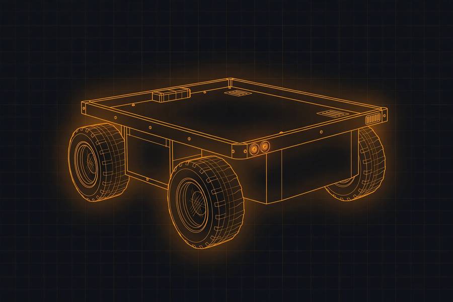
Pathfinder
Evidence: the recorded runs and their sources ↓
RobotForge's own demo robot — an original design, not a copy of anything: a four-wheel skid-steer rover for warehouse aisle patrol, described in one plain paragraph and built entirely by the forge. Entry #004 is ours.
Spec
| Battery | LiPo 14.8 V (4S), 5200 mAh |
|---|---|
| Drivetrain | skid-steer — 4 driven wheels |
| Footprint | 0.42 m x 0.31 m, 0.18 m tall |
| Mass | 3.4 kg |
| Motors | 4x 12 V DC gearmotors |
| Sensors | ultrasonic ranger (front), IMU (centre) |
| Wheels | 100 mm diameter x4 |
examples/pathfinder.jsonRobotForge's in-repo reference design (examples/pathfinder.json), authored for the hackathon demo.GateA pass/fail test in the Gazebo simulator: the twin drives 1 m, turns 90° and stops, and the result is measured against where it really went. runs
Measured against simulator ground truth at the locked thresholds: pass ≤ 5% / 5°, fail over 10% / 10°. The gate tests the spec's simulated twin, not a physical robot.
| Run | Drive vs truth | Turn vs truth | Odometry distance | Odometry heading |
|---|---|---|---|---|
| Run 1 | 1.500% | 4.770° | — | — |
| Run 2 | 1.375% | 2.205° | — | — |
- Run 1: Gate verification on scythe, 2026-10-26 (bindings transport, locked thresholds)
- Run 2: Gate verification on scythe, 2026-10-26 (repeat run)
HarnessThe robot’s wiring. The harness check adds up current on each power rail and flags wires that are too thin or rails that are overloaded. checks
Electrical checks over this robot's documented wiring. Not a simulation; the headline is counts, never a blanket pass.
0 checked clean · 0 with warnings · 0 with errors · 0 partial · 21 not checked · missing data: cable.gauge_awg ×8, connector at both ends (connector_from / connector_to) ×7, current_a for motors ×5
Check-by-check counts and missing data
| Check | Checked | Partial | Not checked |
|---|---|---|---|
| voltage drop | 0 | 0 | 4 |
| ampacity | 0 | 0 | 4 |
| logic levels | 0 | 0 | 3 |
| rail budget | 0 | 0 | 3 |
| connector match | 0 | 0 | 7 |
Findings: none — the inputs that could be checked raised nothing. That is not the same as everything being checked; the counts above say how much was.
Missing data — the datasheets still to hunt. A check that could not run says what it needs:
| Missing input | Blocks | Needed by |
|---|---|---|
cable.gauge_awg | 8 | battery -> driver, driver -> motors, battery -> controller, controller -> ultrasonic |
connector at both ends (connector_from / connector_to) | 7 | battery -> driver, driver -> motors, battery -> controller, controller -> driver … |
current_a for motors | 5 | battery -> driver, driver -> motors, driver rail |
current_a for ultrasonic | 5 | battery -> controller, controller -> ultrasonic, controller rail |
cable.length_mm | 4 | battery -> driver, driver -> motors, battery -> controller, controller -> ultrasonic |
logic_v for controller | 3 | controller -> driver, controller -> ultrasonic, controller -> imu |
connection voltage (volts) | 2 | driver -> motors, battery -> controller |
current_a for controller | 1 | battery rail |
current_a for driver | 1 | battery rail |
logic_v for driver | 1 | controller -> driver |
logic_v for imu | 1 | controller -> imu |
rated output current for battery | 1 | battery rail |
rated output current for controller | 1 | controller rail |
rated output current for driver | 1 | driver rail |
Report: catalog/harness-reports/pathfinder.json · checked 2026-10-27 · reproduce with robotforge harness examples/pathfinder.json
Take it apart
Every spec becomes a kit of simple, 3D-printable parts (robotforge cad). This viewer lays the kit out the way the kit's own assembly file does, straight from the spec's numbers — flat views, or in 3D with the toggle. Click any part.
examples/pathfinder.json…Parts kit
The take-apart kit robotforge cad generates from this robot's spec: every part the generator defines, what it does, and the parameters worth tweaking with the values this robot's kit ships with. Each parameter carries the generator's own source label — from spec numbers come out of the spec, derived numbers are computed from them, and assumption numbers are typical values the spec does not carry.
Chassis plate ×1
parts/chassis_plate.scadThe deck everything else bolts to.
420 x 310 mm footprint, 4 mm thick
| Parameter | Value | Where the number comes from |
|---|---|---|
chassis_length_mm | 420 mm | from spec length_m |
chassis_width_mm | 310 mm | from spec width_m |
plate_thickness_mm | 4 mm | assumption — not in the spec |
corner_radius_mm | 6 mm | assumption — not in the spec |
mount_hole_diameter_mm | 3.4 mm | assumption — M3 bolt clearance |
mount_hole_inset_mm | 12 mm | assumption — not in the spec |
Print note: Print flat as modeled. Suggestion: 3-4 walls, ~25% infill.
Wheel ×4
parts/wheel.scadRolls on the ground; one per wheel position on the robot.
100 mm diameter x 32 mm wide, 6 mm shaft hole
| Parameter | Value | Where the number comes from |
|---|---|---|
wheel_diameter_mm | 100 mm | from spec wheel.diameter_m |
wheel_width_mm | 32 mm | from spec wheel.width_m |
shaft_diameter_mm | 6 mm | assumption — typical DC gearmotor shaft; measure yours |
hub_diameter_mm | 40 mm | derived — 0.4 x wheel diameter, for looks/strength |
lightening_hole_diameter_mm | 12 mm | derived — decorative; delete the loop below for a solid wheel |
Print note: Print flat as modeled. Suggestion: print one first and check the shaft fit before printing the rest.
Motor mount ×4
parts/motor_mount.scadSide plate that holds one drive motor so its shaft lines up with a wheel's axle.
48 mm wide plate, shaft hole at axle height 50 mm
| Parameter | Value | Where the number comes from |
|---|---|---|
shaft_center_height_mm | 50 mm | from spec wheel radius (diameter_m / 2) — the axle height above ground |
mount_width_mm | 48 mm | derived — wheel width + 16 mm of plate around the motor |
mount_height_mm | 61 mm | derived — reaches from the ground past the axle to the chassis plate |
mount_thickness_mm | 4 mm | assumption — not in the spec |
shaft_hole_diameter_mm | 6.4 mm | derived — shaft diameter + 0.4 mm slip fit |
flange_depth_mm | 16 mm | assumption — how far the bolting flange reaches under the chassis |
flange_hole_diameter_mm | 3.4 mm | assumption — M3 bolt clearance |
Print note: Suggestion: 40% infill — this part takes the motor's twist. The motor itself is not a printed part.
Ultrasonic bracket ×1
parts/ultrasonic_bracket.scadFront mount carrying the ultrasonic sensor's two round 'eyes' (HC-SR04 style).
twin 16 mm cans, 26 mm apart
| Parameter | Value | Where the number comes from |
|---|---|---|
plate_width_mm | 52 mm | assumption — HC-SR04 module class; not in the spec |
plate_height_mm | 20 mm | assumption — not in the spec |
plate_thickness_mm | 3 mm | assumption — not in the spec |
transducer_diameter_mm | 16 mm | assumption — HC-SR04 can; measure yours |
transducer_spacing_mm | 26 mm | assumption — HC-SR04 can spacing |
transducer_length_mm | 12 mm | assumption — how far the cans stick out |
Print note: Print flat as modeled. Suggestion: the cans are visual placeholders for a real ultrasonic module.
Reproduce it
Run these from a clone of the repository.
robotforge validate examples/pathfinder.json
robotforge urdf examples/pathfinder.json --out build/pathfinder.urdf
robotforge cad examples/pathfinder.json
robotforge run-gate examples/pathfinder.json
robotforge harness examples/pathfinder.json